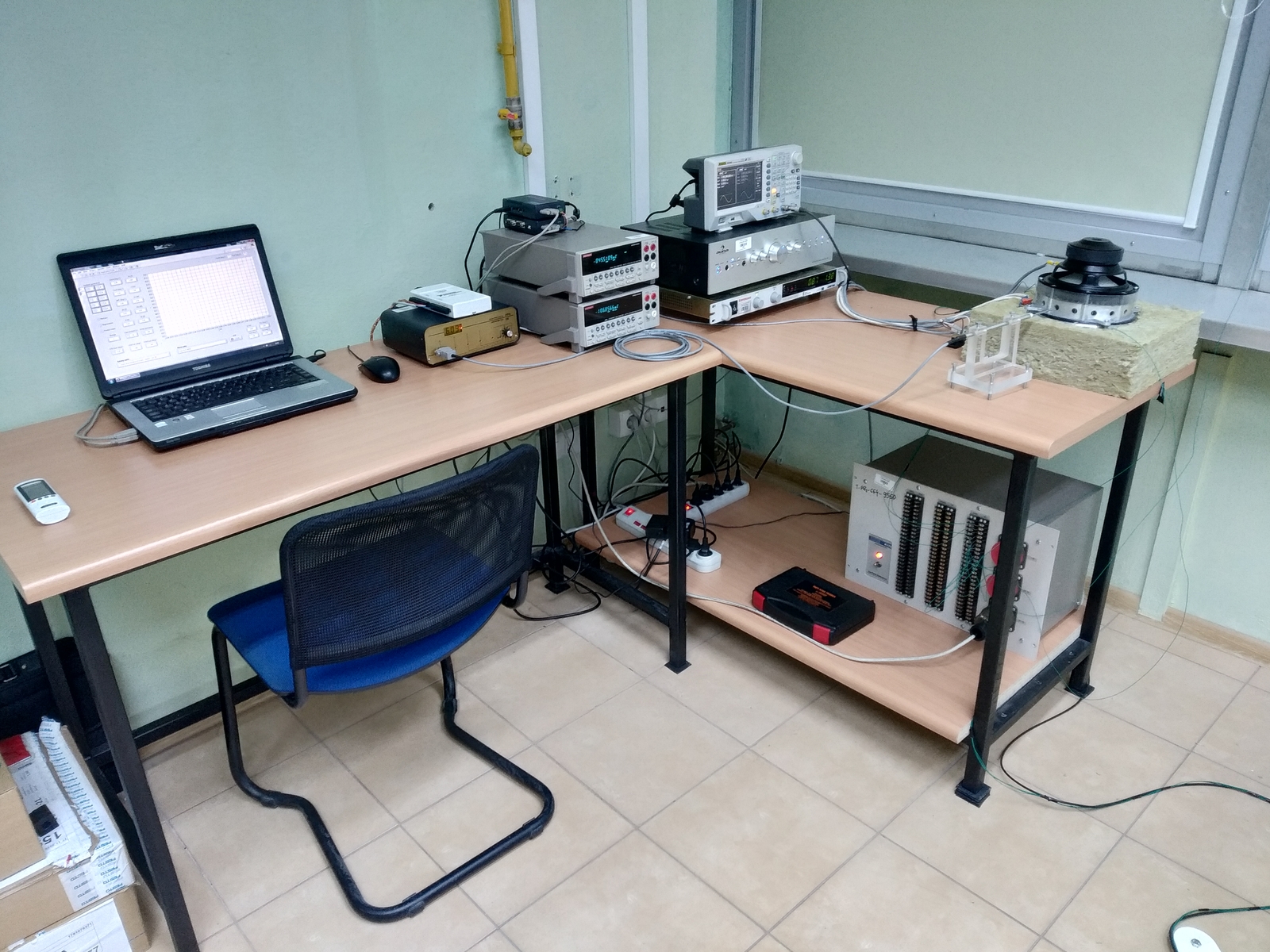
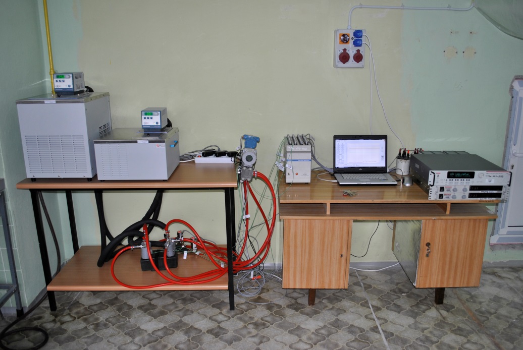
Set-up for determining thermal-flow characteristics of heat sinks.
The set-up enables the testing of thermal and flow characteristics of heat sinks used to dissipate heat from electronic components and industrial LED luminaires. The set-up is equipped with calibrated temperature sensors, heat flux density meters, power supplies and heaters to simulate the heat load. Characteristic velocity measurements can also be made with the use of hot-wire anemometry.
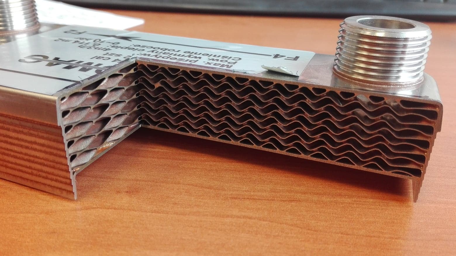
Set-up for determining the thermal characteristics of mini-heat exchangers.
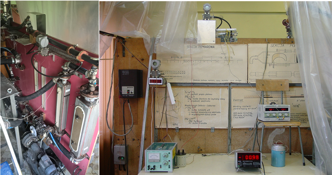
The set-up is used to determine the heat balance of heat exchangers. The main elements are a plate heat exchanger, a set of thermocouples (type K) for measuring the temperature of the medium at the inlet and outlet on the hot and cold side, two pressure transducers, a set of two flow meters and two water thermostats. An automatic ice point was used to stabilize the reference temperature. The parameters measured directly were: temperatures, pressure drops and volumetric flow rates of the medium, on the basis of which the thermal power of the hot and cold side was determined. The process of registration, processing and data acquisition has been fully automated. A Keithley 3700A measurement set with a Keithley 3706 measurement card was used to record the measurement data. For the recording of electrical signals from individual devices, their further processing and data acquisition, a program was created in the LabVIEW environment. Electrical signals were converted into signals of physical quantities by means of functions implemented in the program. The measurements were carried out at a constant value of the ambient temperature, which was set as the average temperature of the exchanger casing. Based on the measurement results obtained, it is possible to further determine the thermal and flow characteristics of various heat exchangers, including mini-channel exchangers.
Electrolytic method.
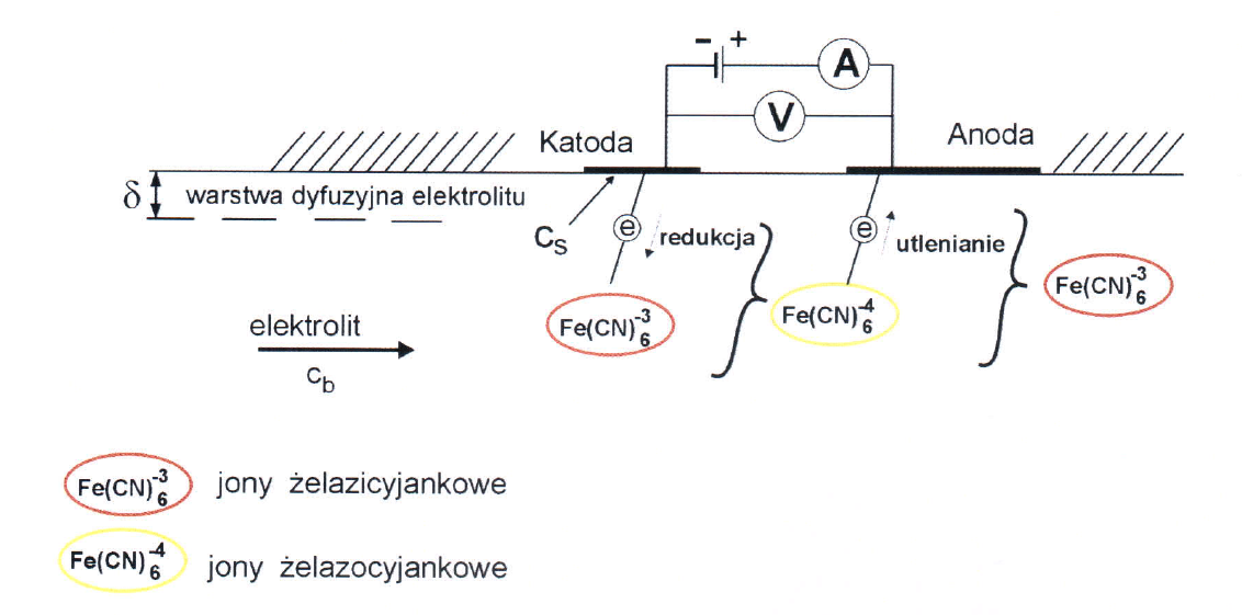
This technique is one of the analog methods used to determine the heat transfer coefficient. It is used when the only way to determine the values of the coefficients are experimental tests. This applies to heat transfer on surfaces with complex shapes and complex flow conditions. In the electrolytic technique (limiting current method), different oxidation-reduction systems are used depending on the Reynolds number Re. The Department of Thermodynamics uses a system in which the tested heat/mass transfer surface is a nickel electrode and the working medium is an electrolyte consisting of an equimolar mixture of K3Fe (CN) 6 - potassium ferrocyanide and K4Fe (CN) 6 - potassium ferrocyanide against the basic electrolyte, which is 1 M NaOH solution. The anode is a nickel electrode with a surface larger than the cathode. The figure shows the processes taking place on the electrodes.
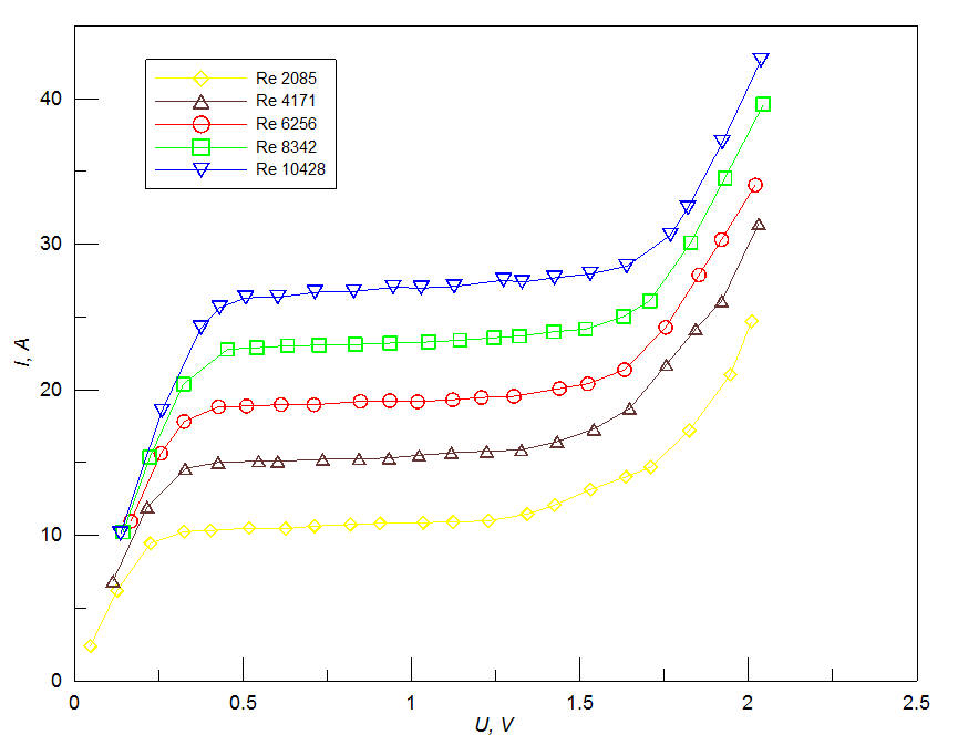
The main relationship in the limit current method, on the basis of which the mass transfer coefficients are calculated. In order to determine the limit currents, voltammograms are prepared from which the values of the limit currents are read. An example of a voltammogram for various Reynolds numbers is shown below. On the other hand, the concentration of working ions in the electrolyte is determined by iodometric titration.
In order to determine the heat transfer coefficients, use the analogy of heat and mass transfer processes with convective flow in the channels. This relationship can be presented in the form of an equation linking the corresponding numbers of similarities for heat transfer with those for mass transfer: Below is a diagram of the station for testing the mass transfer coefficients.
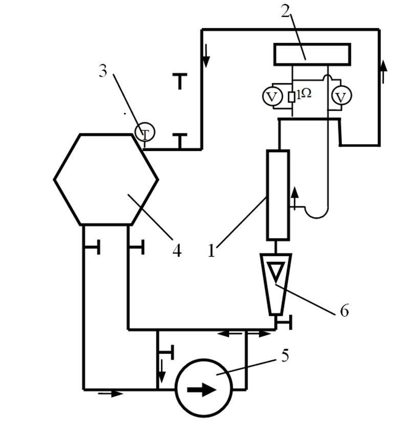
1. Measuring section, 2 - data recording and processing system, 3 - temperature measurement, 4 - electrolyte tank, 5 - pump, 6 - electrolyte flow rate measurement
Measurement of the heat transfer coefficient by electrolytic method.
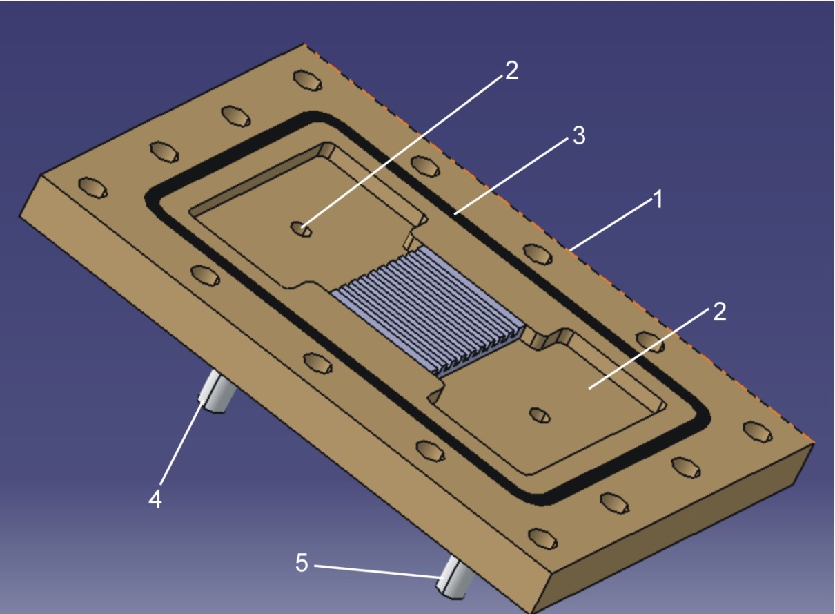
In the case of tests of heat transfer with the flow through mini-channels, significant measurement errors may occur due to disturbances in convective heat transfer processes caused, among others, by installation of temperature sensors, most often thermocouples. Therefore, there is a need to look for other research techniques that would minimize the above errors. One of them is the limit current method, also known as the electrolytic technique, the basis of which is the measurement of the limit current values generated in electrolysis processes running in an electrolyte system, where the cathode surfaces are elements modeling the heat transfer surface in a real phenomenon.
Laboratory for studying the phenomena of convective mass/heat transfer using the naphthalene sublimation technique.
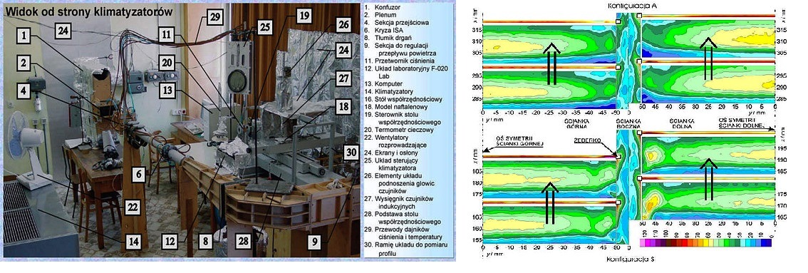
One of the main problems in the analysis of heat transfer issues is the determination of its boundary conditions. In the Department of Thermodynamics, a doctoral thesis was carried out, which dealt with the determination of the influence of certain geometric parameters in channels with finned turbulators on convective heat transfer on its walls. The naphthalene sublimation technique (NST) was used to study the phenomena occurring during such heat transfer. NST is an analog technique based on the similarity of phenomena that are physically different, but identical in terms of their mathematical description. This allows, while keeping the similarity as close as possible, for transferring the measurement results from one physical phenomenon to another. In the case of NST, the phenomenon modeling heat transfer is the phenomenon of mass transfer that occurs during naphthalene sublimation. In NST, a surface model made of naphthalene is exposed to air in flow conditions analogous to those occurring in the modeled heat transfer phenomenon. During exposure, naphthalene sublimes from the model surface in a manner similar to that in which heat flows between the channel wall and the fluid in the modeled phenomenon. The sublime naphthalene flux density is analogous to the heat flux density, and the naphthalene concentration gradient in air is analogous to the temperature gradient. Providing appropriate conditions during measurements allows to determine the naphthalene concentration gradient, and the measurement of the amount of sublimated naphthalene allows to determine the density of the naphthalene stream. In order to perform the measurements, a laboratory that uses NST to study the phenomena of convective heat transfer was established. This technique was previously used in Poland at Poznań University of Technology and the Silesian University of Technology, but currently it is the only laboratory of this type in Poland. The NST Laboratory joined the Department of Thermodynamics to another, equally unique and based on the analogy of heat and mass transfer, laboratory that uses the electrolytic technique for testing convective heat transfer. The NST Laboratory allows to determine the loss of naphthalene using two methods: weight and profile. Thanks to this, it is possible to independently determine the average values of the mass/heat transfer parameters for the channel or its part and their distribution on the model surface. The drawing showing a general view of the laboratory shows elements of several essential laboratory layouts. These are: a wind tunnel operating in a suction and an open system, in which the duct model is exposed to air, a temperature stabilization system ensuring temperature stabilization at a desired level at a selected point in the laboratory with an amplitude not greater than 0.1 K, and a system for measuring the surface profile of naphthalene on models.
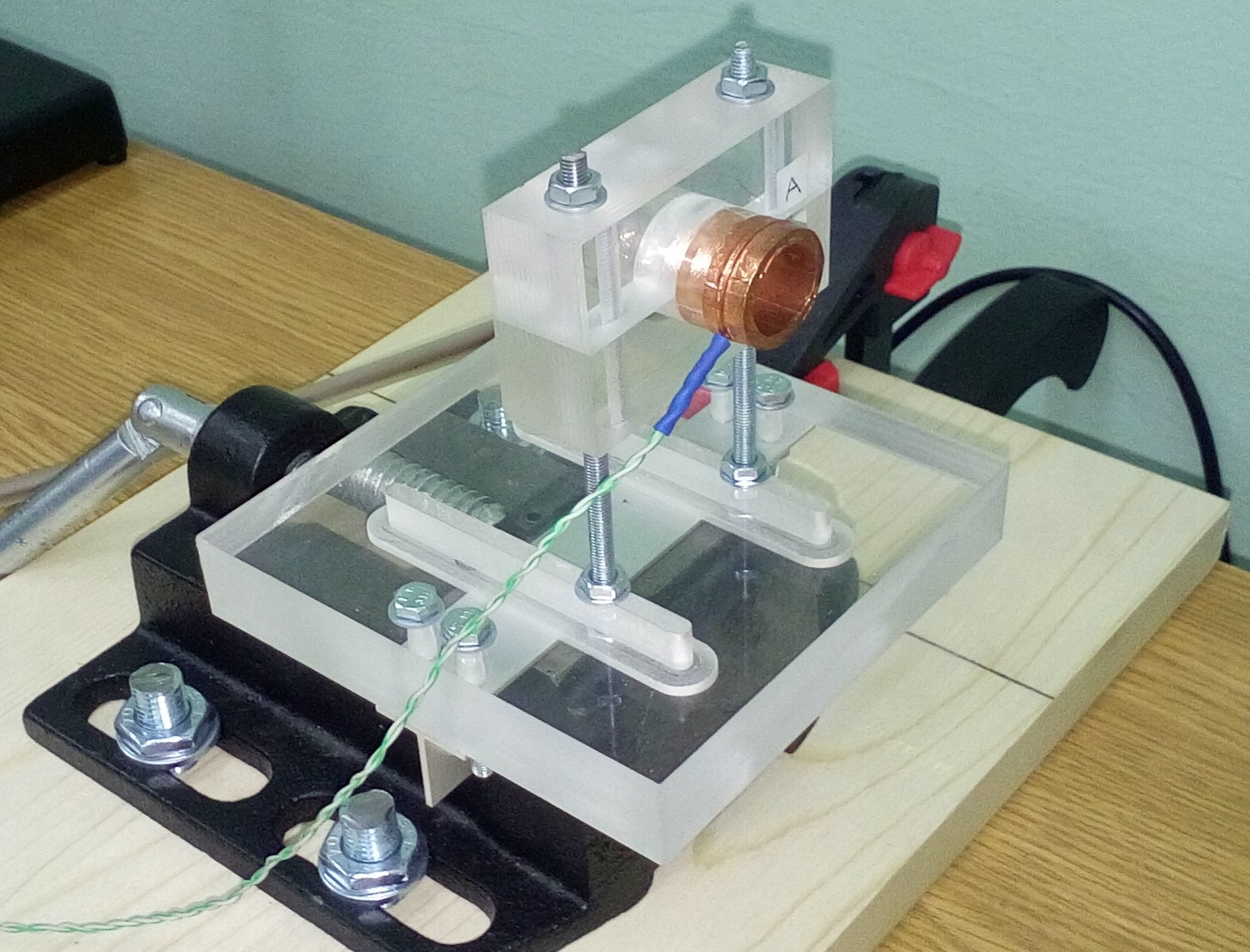
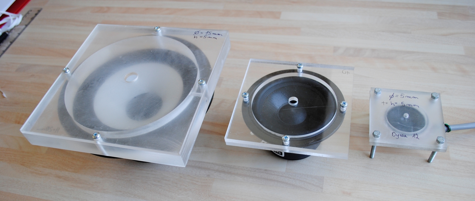
Set-up for testing heat transfer coefficients in impingement cooling with a synthetic jet.
A synthetic jet is a type of flow generated by the path of vortices produced by a synthetic jet actuator. A characteristic feature of the synthetic jet actuator is the lack of an external fluid supply. The average mass flow in the orifice cross section is exactly zero. The device then produces a series of vortices that suck in additional fluid from the environment, causing flow. The synthetic jet actuator consists of three main elements: a vibrating element, e.g. a loudspeaker, a cavity and a orifice.
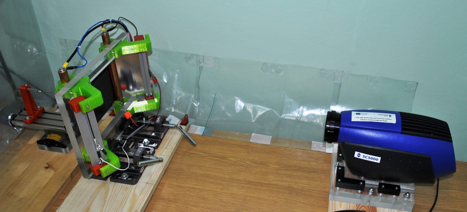
Electrohydrodynamic (EHD) flows.
Experimental and numerical studies of electrohydrodynamic (EHD) flows generated by corona discharge. The analysis of the direct conversion of electrical energy into kinetic fluid energy is based on the electrical and flow characteristics of simple prototypes of EHD fans. A numerical model is also being developed that allows to predict the parameters of this type of devices at the design stage.